20.6.2 DAS Calibration
| Topic Version | 2 | Published | 04/16/2018 | |
| For Standard | PRODML v2.0 | |||
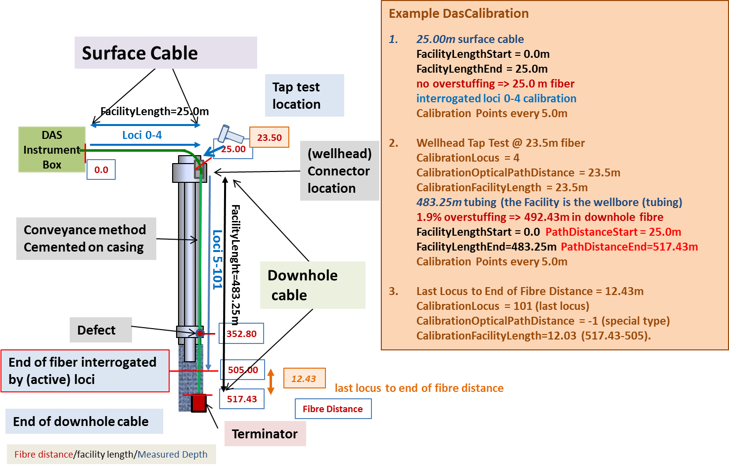
The (optional) Calibration group contains a mapping of loci index to optical path (fiber) distance and facility length. This group can repeat for each facility being measured. The mapping is stored as a set of DasCalibrationPoint structures. A CalibrationPoint structure contains four elements: LocusIndex, OpticalPathDistance , FacilityLength and CalibrationType. The OpticalPathDistance is the distance the light has travel in the fibers, the FacilityLength translates this into a length along the facility (e.g., surface cable, fiber optic cable, pipeline) which corrects for overstuffing, fiber defects, refraction index variations, etc. DAS visualization software can use this table with other metadata to display data in a view familiar to the user (for example, measured depth in a well or location along a pipeline).
- A so-called ‘tap test’ is a test where an operator uses a (spark-free!) hammer to create a vibration on a known location like the well head to provide the interpreter a known point for depth calibration.
- The ‘last locus to end of fiber’ indicates that this calibration point contains the fiber distance from the last locus to the end of the fiber. This is a useful calibrationpoint for permanent downhole installations. The operator can use this measure to create exactly the same interrogation interval along the fiber after a DAS instrument or surface cabling has been changed out of. Note that for this calibration type OpticalPathLength doesn’t mean anything and must be set to a NULL value.
The table below shows how the DAS Calibration object can be used to provide a (very basic) depth calibration for the worked example optical path (which is repeated here for easy reference).
|
Calibration LocusIndex |
Calibration OpticalPathDistance |
Calibration FacilityLength |
Calibration Type |
|---|---|---|---|
|
4 |
23.50 |
23.50 |
tap test |
| 101 | -999.25 | 12.430 | last locus to end of fiber |
| 0 | 5.000 | 5.000 | locus calibration |
|
1 |
10.000 |
10.000 |
locus calibration |
| 2 | 15.000 | 15.000 | locus calibration |
| 3 | 20.000 | 20.000 | locus calibration |
|
4 |
-1.5 |
25.000 |
locus calibration |
|
5 |
30.000 |
29.907 |
locus calibration |
|
6 |
35.000 |
34.814 |
locus calibration |
| 7 | 40.000 | 39.720 | locus calibration |
| ... | ... | ... | ... |
|
99 |
500.000 |
491.143 |
locus calibration |
|
100 |
505.000 |
496.050 |
locus calibration |
The order is flexible, but in this case, the first two calibration points (rows in the table) contain the special calibration types. The remaining rows contain the locus index to optical path (fiber) distance and facility mapping and are CalibrationType set to ‘locus calibration’. Locus index 0 to 4 present calibration points along the surface cable, locus index 5 to 101 the interrogated part of the downhole cable.
The figure above further provides the measured depth derived using these: a surface cable of 25.0 m with no overstuffing on a perfectly flat surface, a downhole cable installed in a perfectly vertical well, with the well head connector 1.5 m above the surface (negative depth), and an overstuffed downhole cable of 483.25m (1.9% overstuffing ~9.182m).