14.3.4 Facility Mappings
| Topic Version | 1 | Published | 12/09/2016 | |
| For Standard | PRODML v2.0 | |||
The purpose of the Facility Mappings element within the Fiber Optical Path object is to represent the relationship between an optical path and the facility(s) (sometimes called “assets”) where the optical fiber has been deployed. For locations where the fiber is used in one facility only, such as a well, the relationship between the facility and the fiber (optical path) is naturally 1 to 1.
However if a fiber (optical path) is long enough that it can cover multiple assets (for example, 2 wells and 1 pipeline, as shown in Figure 14.3.4-1 ) then you must represent that relationship between that one optical path and the 2 wells and the pipeline.
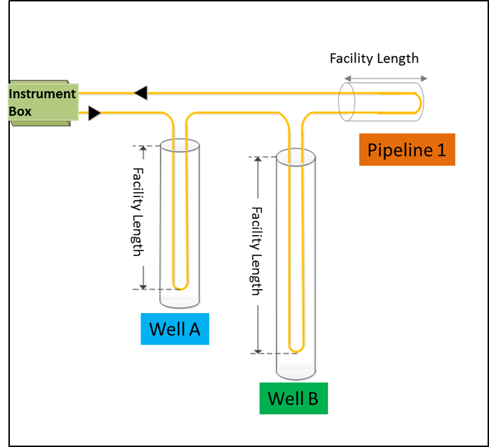
When a PRODML distributed data measurement is obtained, we must be able to map the “optical path length” of the measurement (which gives values along the measured length of the fiber) to the “facility length” of the measurement (which gives distributed values in reference to lengths or depths within the facility, for example in a well, as shown in Figure 14.3.4-1 ).
The Facility Mapping element provides that translation between the actual distance along the optical path as measured from the instrument box and the actual distance of the measurement locations as measured from a reference datum defined for the facility. See the example in Figure 14.3.4-2 wherein the mapping is shown as the grey “facility lengths,” which are formed from certain “optical path lengths” along the total length of the optical path.
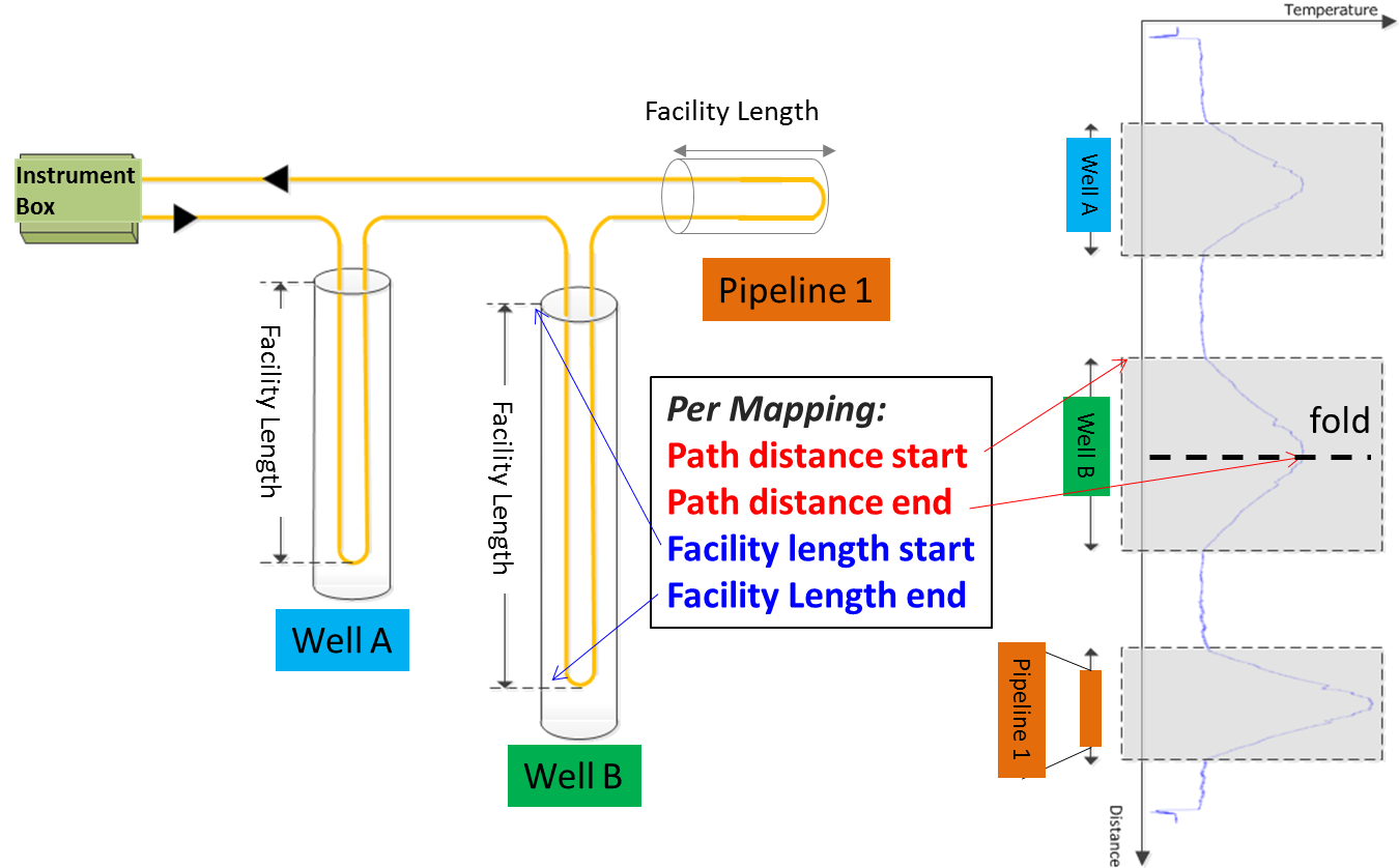
With this arrangement, it is possible to receive a distributed measurement where all the “raw” values are indexed by the absolute distance along the optical path plus the mapping for measurements to be indexed against the distance along the facility.