15.2 Use Case 2: Capturing DTS measurements for Transport and Storage
| Topic Version | 1 | Published | 12/09/2016 | |
| For Standard | PRODML v2.0 | |||
As stated previously, there are two types of measurements that can be obtained from a DTS installed system: 1) the actual ‘raw’ DTS measurement along the length of the optical path and 2) the interpretation log, which has a calculated temperature along the length of the facility only. This section contains examples of XML for representing a DTS Measurement obtained from the installation described in the previous use case.
In the previous use case, we assume the well is 483.25m deep and the entire optical path is 517.43m long. Therefore, it is expected to have a measurement from distance 0 to distance 517.43m and an interpretation log from distance 25m to distance 470m (the sample closest to the last measurement at 505m, see Figure 15.1-1 ).
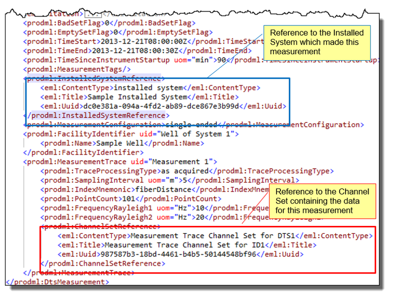
The ‘raw’ measurement traces with stokes, antistokes, and an uncalibrated temperature would look as shown in Figure 15.2-1 . This is the example file DTS Measurement.xml. Note that there can be many traces per DTS Measurement xml. Each has a uid (red box). Optionally, a trace can have an attribute parentMeasurementID which contains the uid of another trace which may be the parent of this trace (in the sense that this trace may have been depth shifted or otherwise derived from the parent).
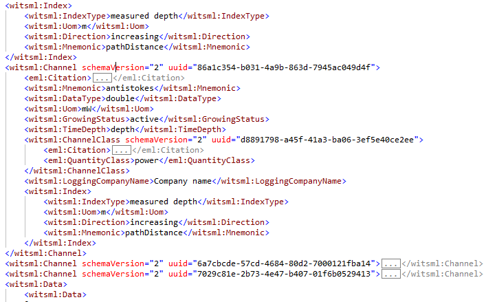
The DTS Measurement object does not contain the actual numerical data—this is instead in a WITSML object called Channel Set (for more details and references, see 14.6 DTS Measurements ). An extract of the channel set object corresponding to the DTS measured traces is shown in Figure 15.2-2 . This shows the Index element, which describes the index, and then the three channels listed above. The first of these is shown expanded (antistokes). This is the example file DtsMeasurement In ChannelSet.xml.
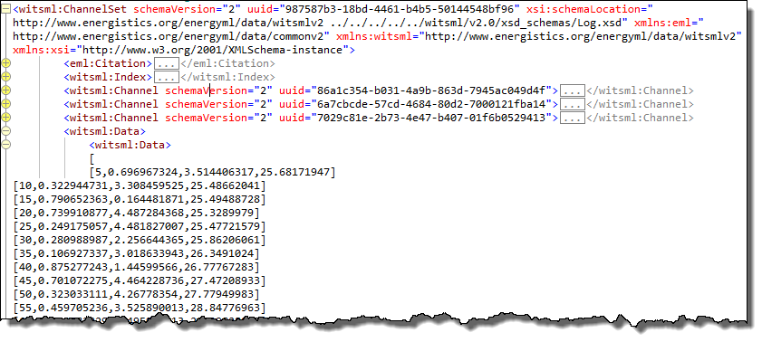
The data then follows (as seen about to start at the bottom of Figure 15.2-2 ), as shown in Figure 15.2-3 . The comma-separated values in the data section correspond to the channels defined previously in this object.
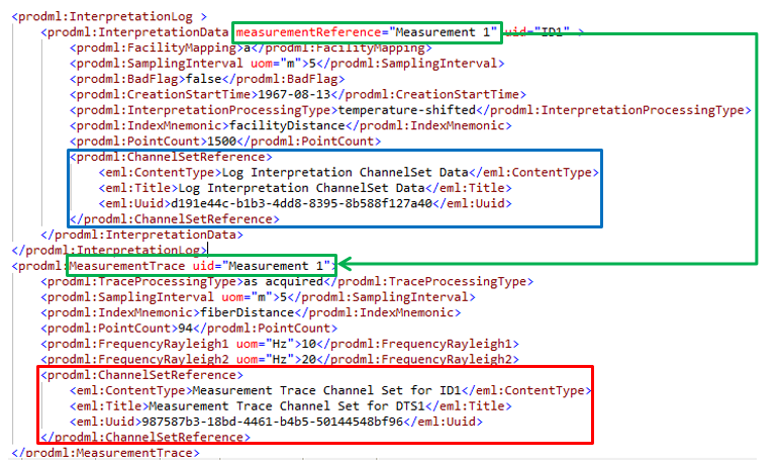
Similarly, an interpreted log is shown in the example file DTS Measurement with Log.xml. This replaces the measurement traces with an interpreted log but is otherwise similar. The data runs from 5m to 470m of facility length (i.e., measured depth in this wellbore), see Figure 15.1-1 . The Channel Set file is DTS Log Interpretation In ChannelSet.xml. See Figure 15.2-4 which shows part of the DTS measurement file. Note the two referenced Channel Sets (red and blue boxes). Note also the IntepretationData has a mandatory measurement reference attribute which contains the uid of the measurement trace from which this interpretation log was derived (green boxes).