25.2.1 Product Flow Model Construction
| Topic Version | 1 | Published | 12/09/2016 | |
| For Standard | PRODML v2.0 | |||
When constructing a Product Flow Model, it is important to differentiate between the “product” type measurements (e.g., oil rate, gas rate, pressure, etc.) which are reported at Ports, and the “facility” type measurements (e.g., motor speed, choke position, valve status, etc.) which can be measured and reported within a unit.
Information about a flow is best reported where it leaves or enters Units (facilities) which may modify the flow (e.g., separators, manifolds etc.). On the other hand facility parameters are internal to the “workings” of a facility.
IMPORTANT: The Product Flow Model assumes:
- Steady state fluid flow across nodes and ports (i.e. pressure is constant across internally and externally connected ports and nodes).
- Conservation of mass across a node or port.
- Pressure can vary internally between ports on a unit.
- Connections between models should be one-to-one so that mass balance concerns are internal to each model.
Construction of a PRODML flow network can be summarized in the following steps, which are further explained below:
- Draw the real world diagram indicating measurement points.
- Draw boundaries to include facility parameters and exclude flow measurements.
- Make each boundary a unit in the flow network and identify the ports.
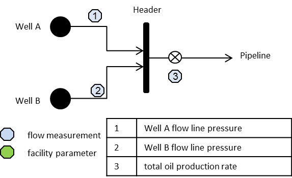
Step 1: Draw the Diagram
First, draw the real-world diagram indicating measurement points (Figure 25.2.1-1).
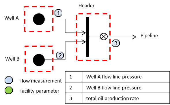
Step 2: Draw Boundaries
The next step is to draw boundaries around items with no flow measurements (Figure 25.2.1-2).
Step 3: Make Each Boundary a Flow Unit
Finally, make each boundary a unit in the flow network and label each unit and node with a unique name (Figure 25.2.1-3).
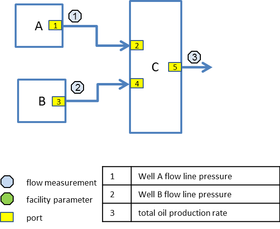
Table 25.2.1-1 summarizes the units of the flow network, assigned unique identifiers, and associated facility kinds.
|
Unit Name |
Unit ID |
Facility ID |
Facility Kind |
Kind Qualifier |
Measurements |
|---|---|---|---|---|---|
|
A |
U01 |
W01 |
well |
(outlet) pressure |
|
|
B |
U02 |
W02 |
well |
(outlet) pressure |
|
|
C |
U03 |
HDR01 |
manifold |
production header |
(outlet) oil flow rate (outlet) pressure |
|
Port |
Direction |
Connected Node |
|---|---|---|
|
1 |
outlet |
A-C |
|
2 |
inlet |
A-C |
|
3 |
outlet |
B-C |
|
4 |
inlet |
B-C |
|
5 |
outlet |
C-P |
|
Port |
Property |
Flow |
Product |
Qualifier |
|---|---|---|---|---|
|
1 |
pressure |
production |
oil |
measured |
|
3 |
pressure |
production |
oil |
measured |
|
5 |
pressure |
production |
oil |
measured |
|
5 |
flow rate |
production |
oil |
measured |
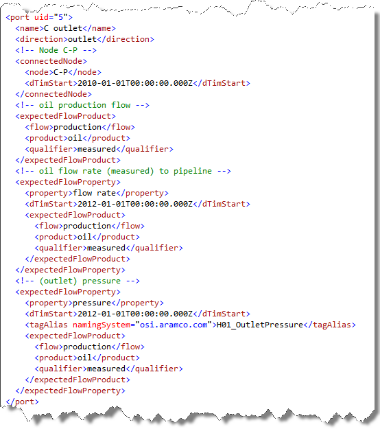
Figure 25.2.1-4 illustrates the definition of port 5 in XML. Note that this snippet shows PRODML v1.x style; the content has not changed in v2.