10.3.2.3 Sealed Volume Framework Representation
| Topic Version | 1 | Published | 09/11/2015 | |
| For Standard | RESQML v2.0.1 | |||
Use this representation to define a volume representation of a consistent stratigraphic organization interpretation. Using this representation as a starting point gives gridding software a detailed clean topology and geometry framework and avoids inconsistent geometry usage. When several nodes are topologically associated, they have absolutely the same geometry, even if they belong to different representations of “structural objects”.
By delivering a sealed volume framework representation, a software package validates a consistent understanding of the geological stratigraphy interpretation on which property estimations, fluid flow simulation, and basin modeling can be conducted.
Note that the sealed volume framework representation is based on a sealed surface framework representation.
The sealed volume framework representation is described as a boundary representation (BREP): (http://en.wikipedia.org/wiki/B-rep ). It contains surface contact representations (volume/volume contact interpretations between rock feature interpretations (stratigraphic units, geological bodies, fluid units) and volumes defined by shells.
Figure 10.3.2.3-1 shows the UML model for the sealed volume framework, which is explained below. Figure 10.3.2.3-2 is a graphical example of a sealed volume framework.
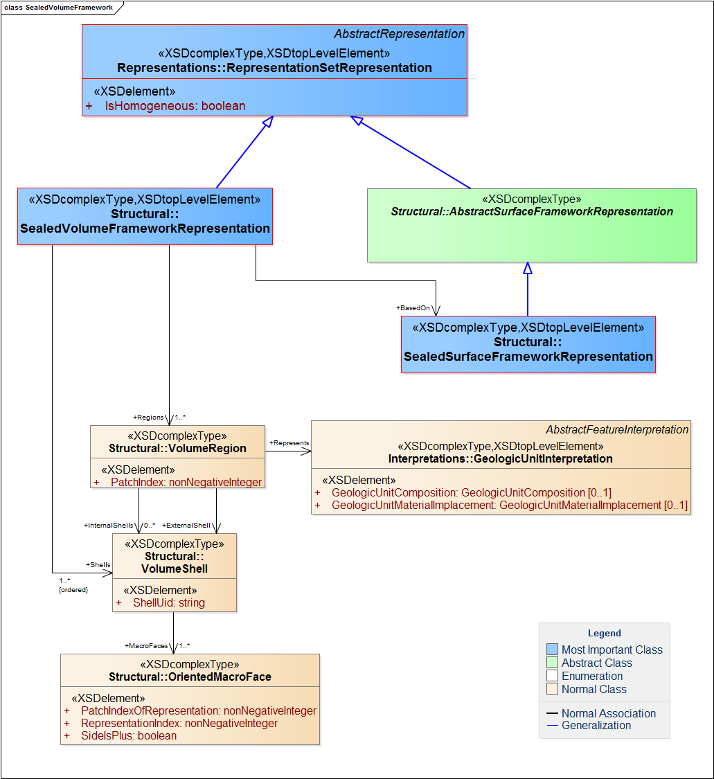
A sealed volume framework representation can be composed of several volume regions, each of which represents a rock feature interpretation (a geologic unit interpretation for the geosciML standard (http://www.geosciml.org/ ).
Each volume region has one external volume shell and can have several internal volume shells.
A shell is composed of the sealed contact representation parts defined in the sealed surface framework representation on which this sealed volume framework representation is based, and by oriented macro faces. An oriented macro face is an element of a volume shell that is defined by a set of oriented faces belonging to boundable patches.
A macroface may describe a contact between:
- two structural, stratigraphic, or fluid units.
- one boundary feature (fault or frontier) and a unit.
This oriented macroface can be described by one patch of an individual representation. To indicate the right surface, the writer software must specify (by a representation index) from which representation patches are “extracted” and must specify which patch is involved by giving its patch index representation.
Usually, a macroface is a bounded open subset of a plane or a curved surface in 3D, delimited by an outer contour and zero and one or more inner contours describing holes.
