11.7.2 Finite Element Subnodes
| Topic Version | 1 | Published | 09/11/2015 | |
| For Standard | RESQML v2.0.1 | |||
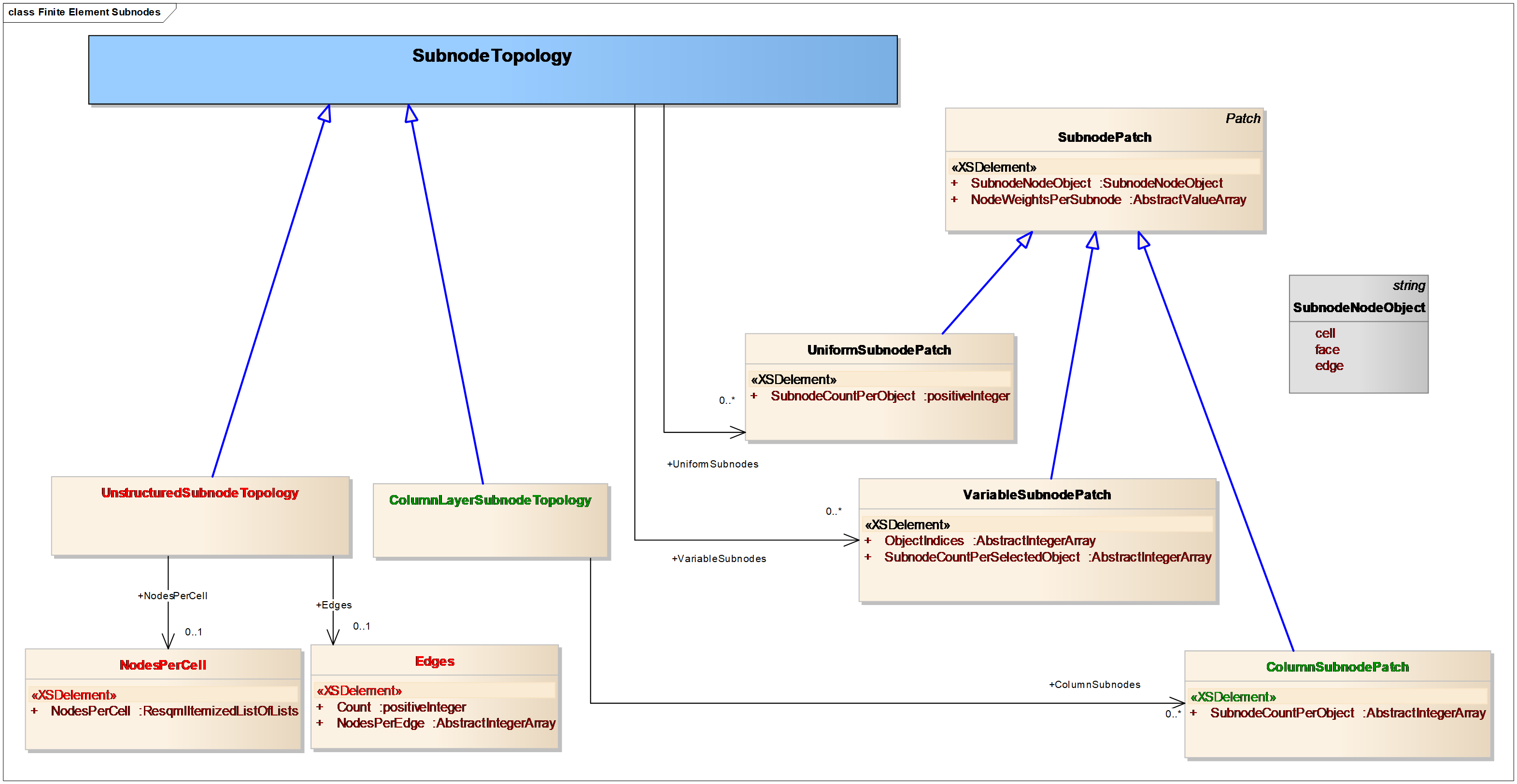
Subnodes are used in RESQML to introduce additional degrees of freedom to represent either higher order finite element geometry or properties (Figure 11.7.2-1).
A subnode is defined with respect to an ordered list of nodes specified by the reference
subnode node object. For example, if there are N reference nodes, then a subnode is defined by
N parametric weights. For visualization purposes, the inferred location for the subnode is at
the weighted average location of all of the nodes 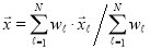
. When RESQML attaches a point to a subnode, it replaces this implicit position with an explicit position.
The additional geometry attachment also includes cells, edges, and faces. These attachments use implicitly defined subnodes with parametric weights equal to unity on the respective objects. This approach is useful, for example, to describe a face subnode defined at the parametric center of each face, irrespective of the number of nodes per face, which may vary from face to face.
The choice of subnode object controls the node count per object for each subnode. Before subnodes may be defined for an object, an ordered list of nodes must first be defined or otherwise known for the same object. The known ordered lists of nodes may vary from grid class to grid class. For example, an ordered list of nodes per cell can be inferred for any of the column-layer grids, but not for the unstructured grids. By construction, such an ordered list is always known for the face nodes, but need not have been defined for nodes per cell or nodes per edge.
The number of subnodes per object may be as uniform or as variable as the associated objects. For uniform subnodes, the count of subnodes is identical for each object. An example is an edge subnode describing a cubic spline, with two nodes per edge and two subnodes per edge, giving a total of four node weights that need to be specified. Column subnodes allow the number of subnodes to vary by column within a grid, while the variable subnodes object allows the number of subnodes to vary per object.
The continuity of the subnode geometry or property is controlled by the choice of subnode object, which may be cell, edge, or face. For example, if the choice is cell, then the geometry or a property associated with a cell subnode has no continuity to adjacent cells. This is how a discontinuous finite element basis is constructed. For continuous finite elements, either face or edge nodes are used, where the continuity of the basis follows the continuity of the object specified.
Subnodes are patches. Grid topology allows the definition of independent subnodes of multiple kinds. To provide more specificity on the subnode geometry or property attachment, subnodes are defined with patch indices, which should provide a unique specification to the attachment.