12.7.1 Class Diagram
| Topic Version | 1 | Published | 09/11/2015 | |
| For Standard | RESQML v2.0.1 | |||
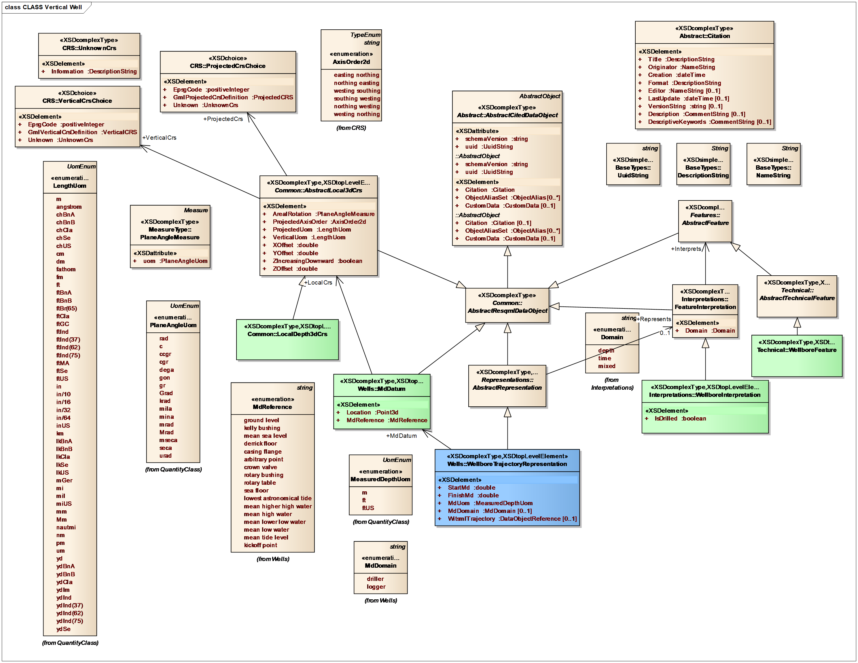
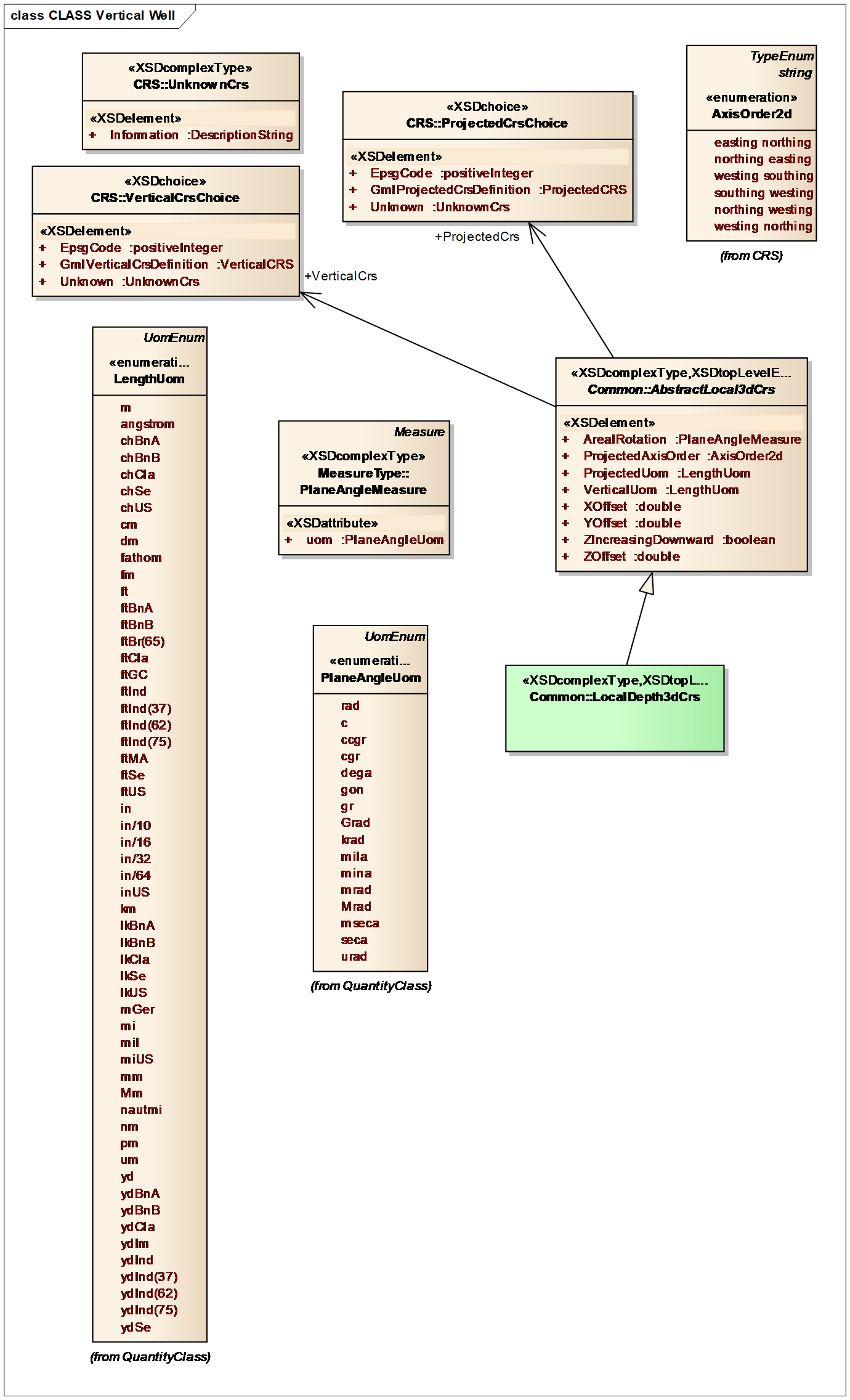
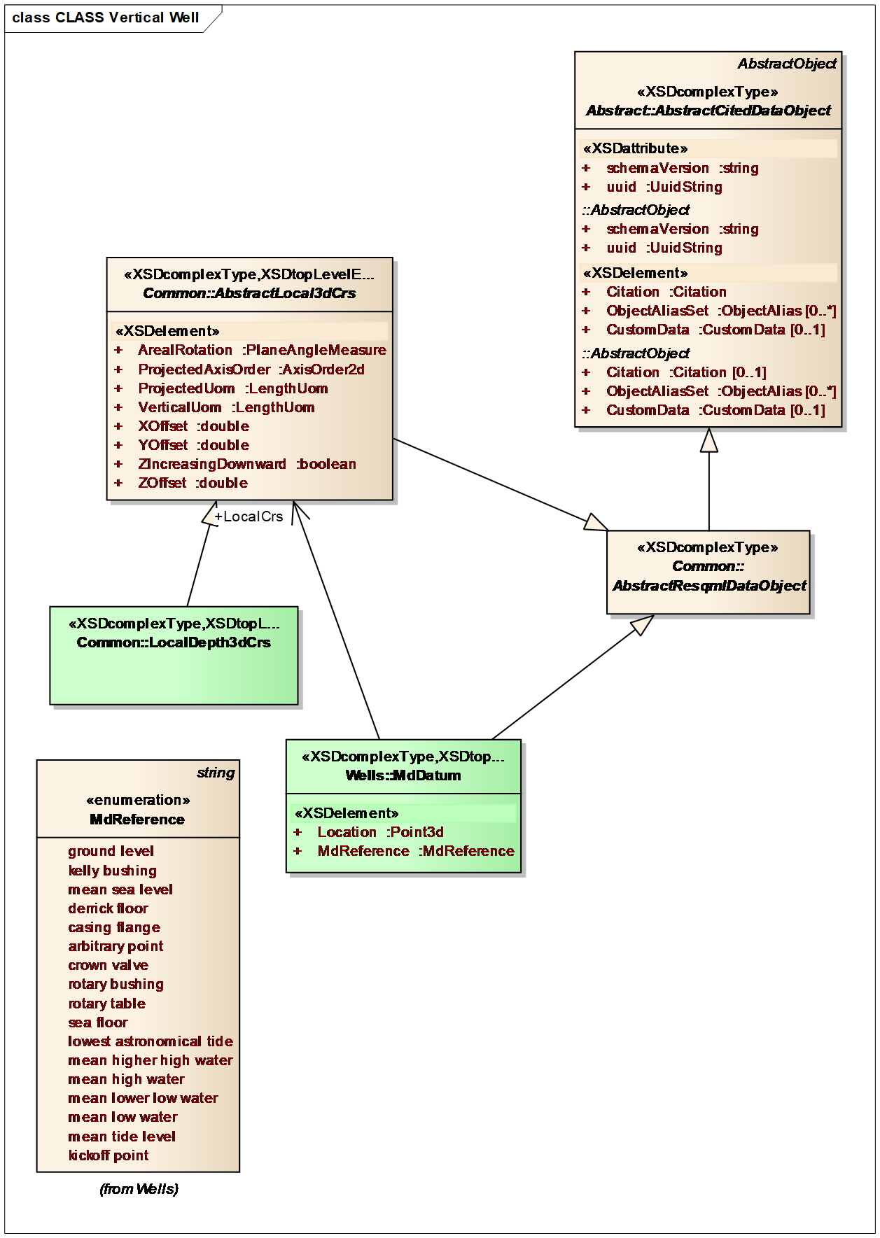
The single major mandatory component of the wellbore trajectory representation is the MD datum (Figure 12.7.1-3), which corresponds to the wellhead. The MD datum exists independently of the wellbore trajectory representation and needs to have a uniquely defined local 3D coordinate reference system (CRS) (Figure 12.7.1-2).
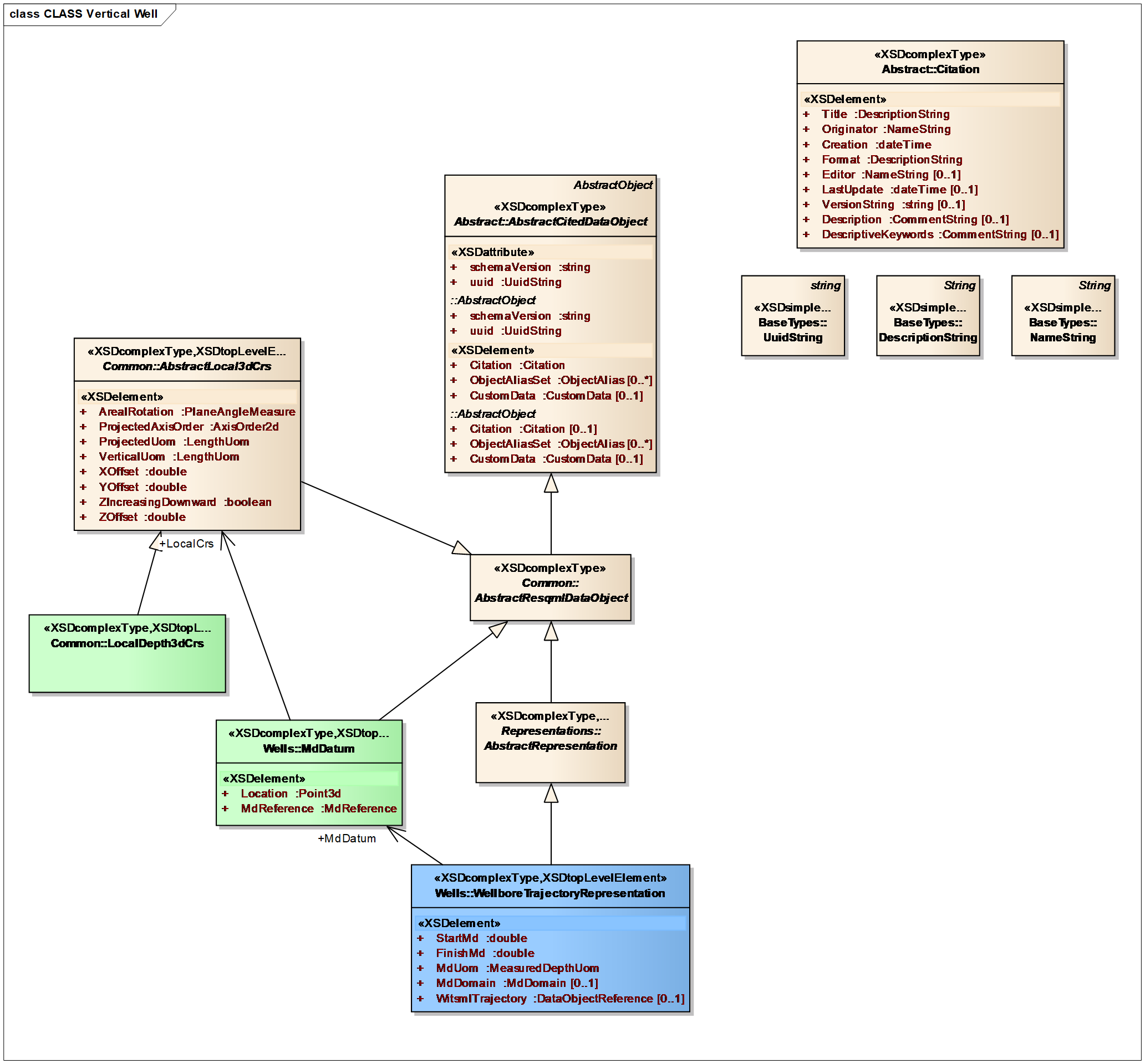
The vertical well geometry (highlighted cells and Figure 12.7.1-4 ) is known from the location of the MD Datum and the measured depth range (start and finish MD values) of the wellbore trajectory representation. In this specific case, there is no need to specify a parametric line to describe its geometry.
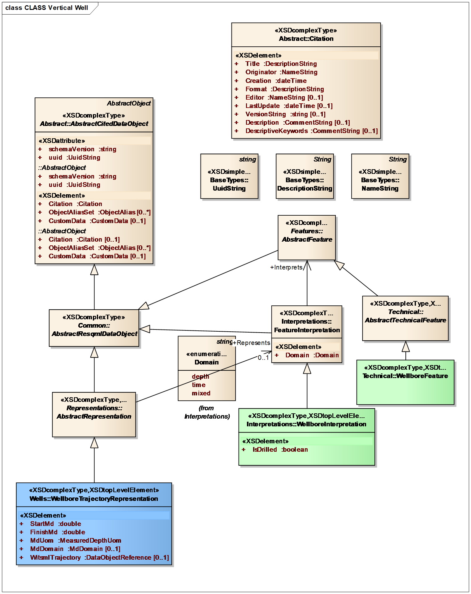
Finally, the use of wellbore interpretations and features (Figure 12.7.1-5) allows us to document relationships between wellbore trajectory representations. For example, multiple representations with a shared interpretation may arise, if we have three ways of representing nominally the same geometry: a minimum-curvature trajectory, a piecewise linear trajectory at a low resolution corresponding to the intersections with a coarse reservoir simulation grid, and a piecewise linear trajectory at high resolution corresponding to the intersections with a detailed 3D geologic model. Wellbores that share the same feature but different interpretations may correspond to a single nominal target well and the many well plans for that well.