13.2 Seismic Lattice Representation
| Topic Version | 1 | Published | 09/11/2015 | |
| For Standard | RESQML v2.0.1 | |||
As a feature, there is no requirement to define an equivalent 1D index from the inline and crossline indices. However, there is a requirement to do so as a representation. (For more information in grids, see 11 Grids .)
Two types of representations may be used to provide the actual geometry of surveys:
- The 2D representation is a grid 2D representation where the geometry is provided by a 2D lattice. When using a grid 2D representation, inline/crossline corresponds to the fastest/slowest indices, respectively.
- The 3D representation is an IJK grid representation where the geometry is provided by a 3D lattice, which corresponds to the geometry of a 3D volume. Because the fast axis (I) in a seismic volume corresponds to vertical traces, inline/crossline typically corresponds to the J/K indices, respectively, although the details will vary depending upon the selection of columns or pillars, as discussed in more detail below.
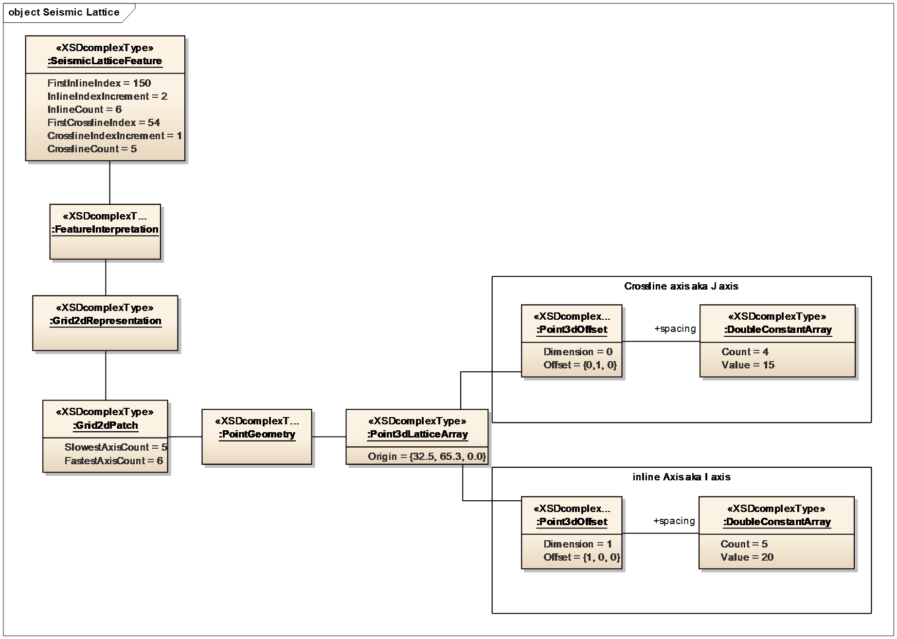
At the representation level, the dimensions of the seismic lattices are typically regularly spaced. The indexing of these two dimensions is very constrained; the origin indices are always 0,0 and the increment between two node indices is always equal to 1.
Because the lattice geometry is based on axes defined by vectors, the direction of these vectors provides the angular information usually associated with a survey, such as the rotation relative to the local CRS.
Figure 13.1-1 shows how we use an array lattice of points 3D (ArrayLatticeOfPoints3d) to define the geometry of the representation of the survey. Figure 13.2-1 is an example instance diagram of a seismic lattice.