13.6.2 Interpretation from a 2D Line
| Topic Version | 1 | Published | 09/11/2015 | |
| For Standard | RESQML v2.0.1 | |||
In this scenario, the main difference is basically that we have no seismic 3D block at all but only the 2D section.
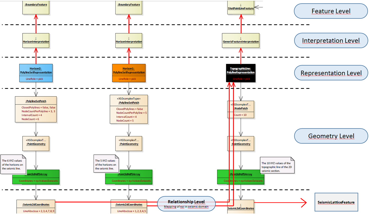
Referring to Figure 13.6.2-1 , in RESQML, this scenario leads to 3 top-level data objects: two boundary features (BoundaryFeature) for interpreted horizons and a shot point line feature (ShotPointLineFeature) for the selected seismic line. Those 3 features will each have an appropriate interpretation.
The most important design choice is in the representation and the geometry structures. For the shot point line feature, the representation is a polyline representation and the picked 3D points are stored in a NodePatch at the resolution of the seismic 3D (10 voxels in this sample case). For both horizons, the representation is a polyline set representation and the valued 3D point geometry is stored in a polyline set patch.
Each horizon valued 3D point is mapped to corresponding 2D seismic coordinates in the polyline representation of the shot point line feature. The 3D picked points defining the 2D seismic section are mapped to corresponding 3D seismic coordinates in the seismic lattice feature which defines the seismic survey.