19.5.2 Overview of the HDF5 File
| Topic Version | 1 | Published | 04/16/2018 | |
| For Standard | PRODML v2.0 | |||
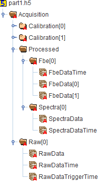
Figure 19.5.2-1 shows how the DAS data for a single acquisition is captured in an HDF5 tree structure.
At the root level of the HDF5 file, it must contain one attribute “uuid” which is the unique reference linked to the file proxy reference in EPC.
The main branches describe the Raw group and Processed data group with Spectrum and FBE groups being branches of the Processed data group. The Raw, Spectrum and Fbe groups each have branches for their ‘data’ and ‘time’ arrays. Note that for FBE data a single time array for all frequency bands under that branch.
Further the figure shows Calibration attribute branches which capture data to locate loci along the optical path in relation to the facility being measured.
The DAS acquisition model also allows a Custom branch (not shown in Figure 19-5) to be added under the Acquisition root level to describe DAS vendor specific information not captured in the current model.
NOTE: The screen shots of HDF5, XML and EPC files in the following sections are taken from the worked example, which has:
- 1 raw array, which is split over 2 physical HDF5 files
- 1 processed FBE data set containing 2 bands of FBE data
- 1 processed spectrum
The cardinality for this data is listed here. Note that the pattern shown here remains the same but the specific cardinalities of arrays changes for other examples:
- Custom
- Calibration 0..* (none to many - two groups in this example)
- RAW group is 0..* (One group in this example)
- FBE groups is 0..* (One group in this example).
- FBE bands within an FBE group is 1..* (Two bands in this example)
- Spectra is 0..* (one in this example)
Further note that the start index is always zero for the first index, e.g., Fbe[0] for frequency band one, Fbe[1] for frequency band two, etc.
