14.2.1 Data Model Overview
| Topic Version | 1 | Published | 12/09/2016 | |
| For Standard | PRODML v2.0 | |||
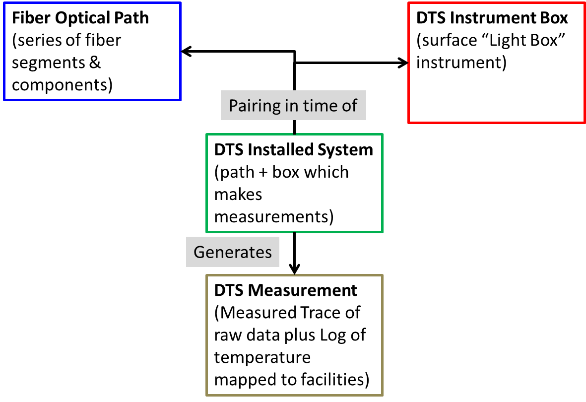
Figure 14.2.1-1 is a simple diagram of the data model for a DTS implementation. The colored boxes represent the minimum set of objects in the DTS data object that are needed to represent any DTS deployment. The meaning and usage of the colored boxes is explained in the next section of the document.
Each of these boxes is covered by a top-level object in the data model:
- Fiber Optical path
- DTS Instrument box
- DTS Installed system
- DTS Measurement