14.3.3 Optical Path Network Representation
| Topic Version | 1 | Published | 12/09/2016 | |
| For Standard | PRODML v2.0 | |||
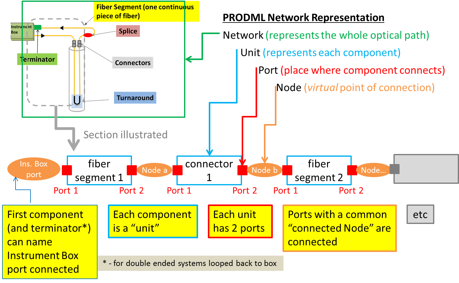
The optical path network is represented by a PRODML Product Flow Model (a standard object for networks in PRODML) (Figure 14.3.3-1). This model uses the concept of units, which are “black boxes” that have ports, representing connection points. Each component in the inventory that is part of the optical path is represented by a unit. Connectivity is represented by nodes, which are virtual objects representing the connection between two ports.
Generally along the optical path, all the components have linear connectivity so units have 2 ports. One benefit of this approach is standardization with other network representations, e.g., the flow network of PRODML.
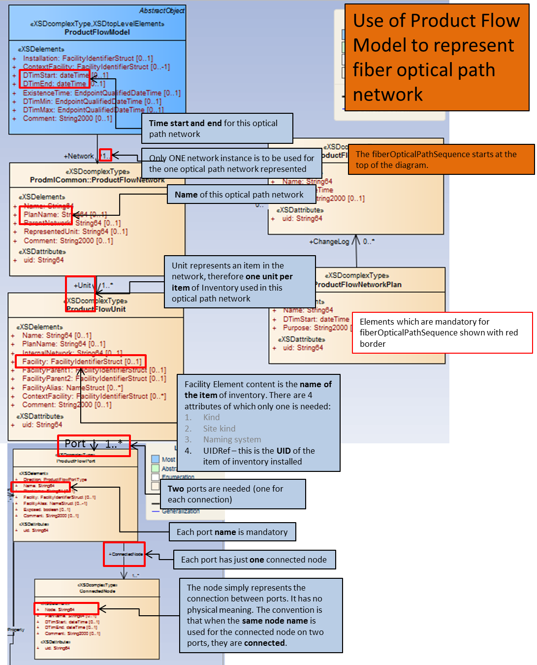
For the UML model that represents this network, see Figure 14.3.3-2 . This diagram also shows the mandatory elements and notes as to which convention to follow.
Note, the connectedNode element for two ports on different units indicates these two units are connected. Example, “Port 2” of “fiber segment 1” and “Port 1” of “connector 1” both show connectedNode as “Node a”. The first component can reference a specific named port on the instrument box if required to report this, and the same applies to the port on the terminator if “looped back to instrument box”. This way the instrument box connections are reported.