6.2.3 Defining the Hierarchies
| Topic Version | 1 | Published | 12/09/2016 | |
| For Standard | PRODML v2.0 | |||
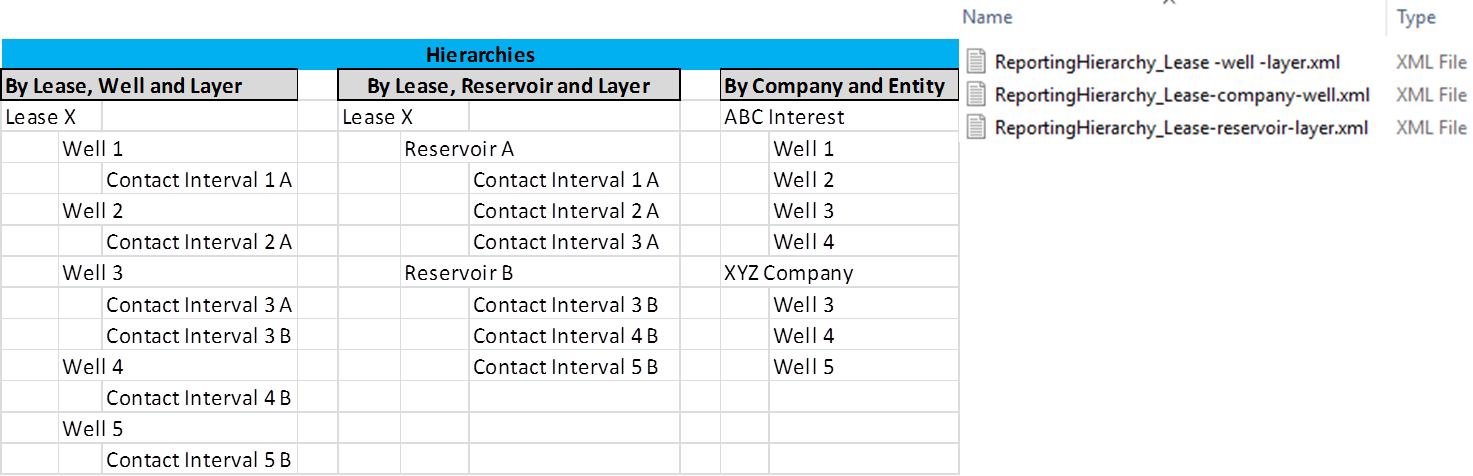
The worked example contains 3 example hierarchies. As noted above, any number can be created to show the context of the reporting entities. Figure 6.2.3-1 shows the hierarchies included. The left side of the figure lists the hierarchy names and underneath, the hierarchy of nodes. The right side shows these as 3 XML data objects of type reporting hierarchy. These can be found in the sub-folder “ReportingHierarchies”. The 3 hierarchies demonstrate:
- Typical order for volume reporting: lease (field)/well/contact interval (layer)
- Order for reservoir offtake reporting: lease (field)/reservoir/contact interval (layer)
- Order for commercial relationships, e.g. for defining access to data: company (commercial entity)/well
Again, you only need to update the hierarchy object when changes are made (e.g., a new well comes on line, etc.).
Note that the third hierarchy supports the requirement of Use Case 5 and 6 (see 4.2 Use Cases: Overview ) in which reporting is done via a third-party “hub”. This hierarchy makes it possible to list all the commercial entities associated with the asset being reported, and which require access to data pertaining to particular reporting entities, e.g., the different well interests shown in Figure 6.1-1 .
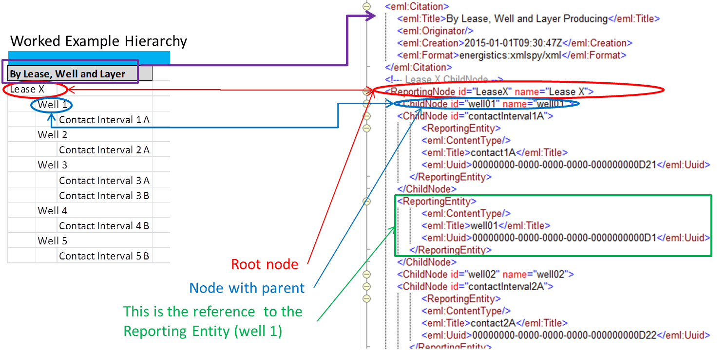
The structure of a hierarchy data object is shown in Figure 6.2.3-2 . The left side of the figure shows one of the example hierarchies. The right side shows some of the XML hierarchy data object. Note:
- The root node of a hierarchy is the reporting node (red circle).
- Child nodes nest under this root and each other (blue circle).
- The use of reporting entity as the data object reference back to the reporting entity object (for well 01 in this example) using UUID (green box).