11.16 Grid Connection Set Representation
| Topic Version | 1 | Published | 09/11/2015 | |
| For Standard | RESQML v2.0.1 | |||
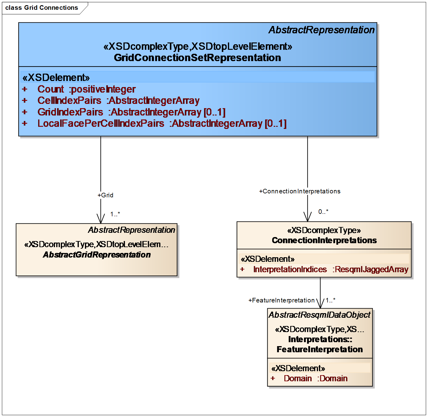
Grid connection sets are RESQML representations (Figure 11.16-1) used to represent some cell-to-cell connections on a grid. A main use case is describing the cell-to-cell connections where the fluid flow is impacted due to a fault, which includes the concept of non-standard adjacency (NSA) also known as non-neighbor connectivity (NNC). As with any other representation, grid connection sets may be used to support properties or relationships. Unlike a grid, geometry as such is never attached to a connection, although geometric properties, i.e., cell face overlap area, may certainly be attached to a connection.

Grid connection sets are the preferred RESQML method for representing the impact of faults on fluid flow within a grid, and are preferred over the use of grid cell-face sub-representations. (The use of cell-face-pairs is more complete than single cell-faces, which are missing a corresponding second cell face identification, and only provide an incomplete representation of the topology of a fault.) RESQML allows a couple of options for specifying grid connection sets; recommended best practice is to specify a single grid connector set that contains all faults and other important cell to cell connection. To describe more complex structures (e.g., faults or geobody boundaries, potentially merging at below the spatial resolution of a grid) you can associate zero or more interpretations with the individual connections (explained in more detail below).
BUSINESS RULE: A single cell-face-pair should not appear within more than a single grid connection set. This rule is designed to simplify the interpretation of properties assigned to multiple grid connection sets, which might otherwise have the same property defined more than once on a single connection, with no clear means of resolving the multiple values.
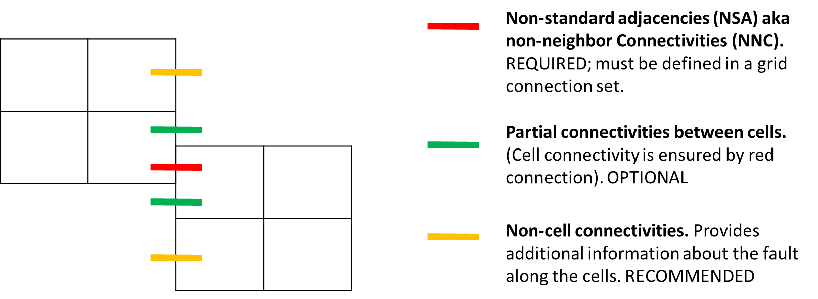
The current construction provides a list of connections between cell pairs; for requirements and options for NSA/NNC, see Figure 11.16-2 . There is no requirement that the two cells are on a shared grid, and so the grid index may need to be provided for each cell. The grid index object is used to convert a list of grid UUIDs to local grid indices, by pairing a (locally) unique index with a reference to a grid. Because directional information is often needed for the use of a connection, the local face per cell index is also included. This is a local index, which, for example, would take on the values of 0…5 for an IJK grid cell.

The connection interpretations provides the feature-interpretations, and hence the feature’s name. Notice that the interpretation data structure allows more than one interpretation to be associated with a single connection, which may be required depending upon the spatial resolution of a grid. In engineering terms, the implications are that the transmissibility multiplier for a connection may need to be computed as the product of transmissibility multipliers for each fault or feature-interpretation.
The connection interpretations object may be used to associate feature-interpretations with individual connections. The ordered list of feature-interpretations defines a 0-based index for each interpretation, which are then referenced from the interpretation indices array so that each connection has zero, one, or many associated interpretations.