12.7.2 Instance Diagram
| Topic Version | 1 | Published | 09/11/2015 | |
| For Standard | RESQML v2.0.1 | |||
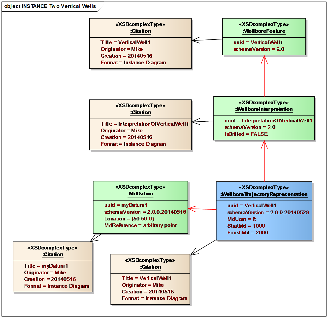
Figure 12.7.2-1 shows the instance diagram of this two-well example, which is expanded into the two parts of Figure 12.7.2-2 and Figure 12.7.2-3 .
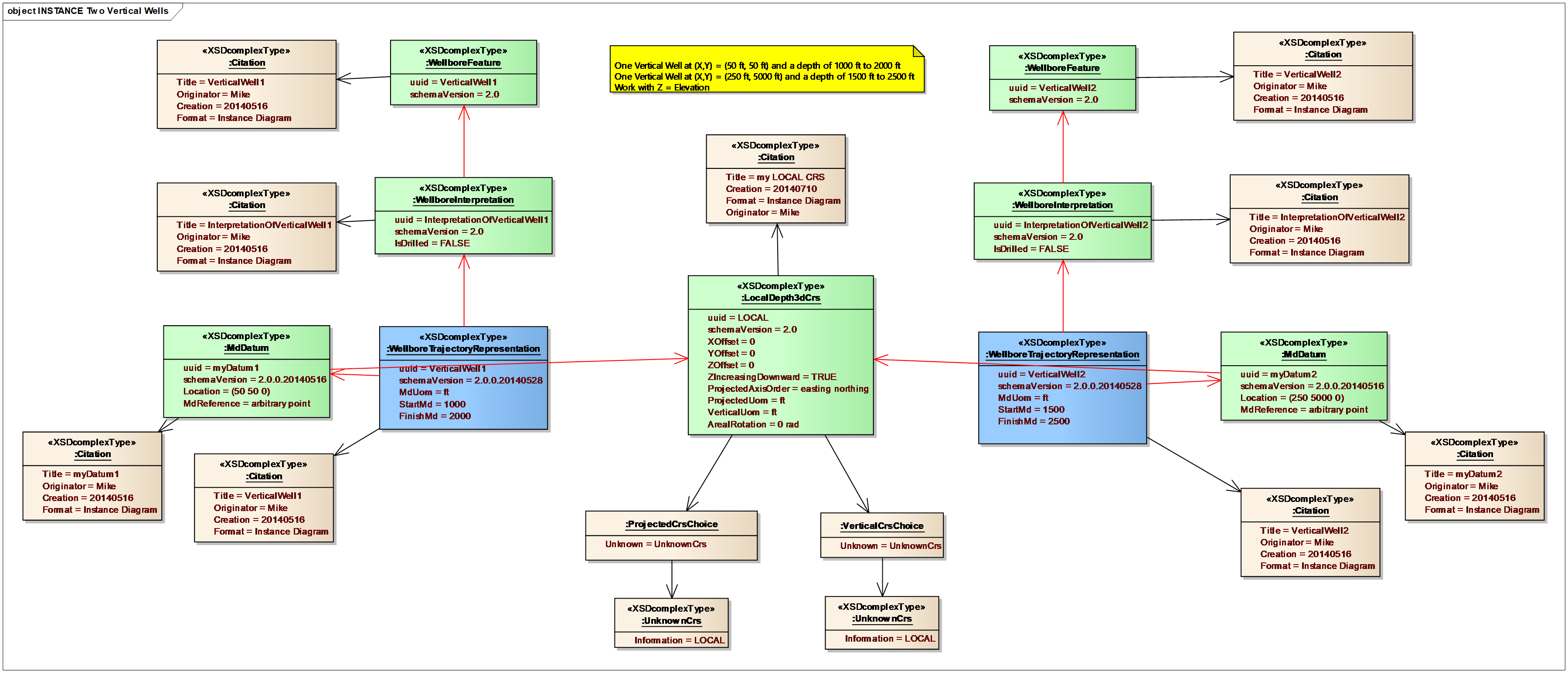
In Figure 12.7.2-2 , we can see that one well is located at a surface position of (50 ft, 50 ft) in the local coordinate reference system, and extends from a depth of 1000-2000 ft. The other is at a surface position of (250 ft, 5000 ft) and extends from a depth of 1500-2500 ft.
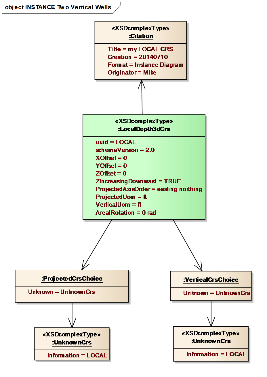
For this specific example (Figure 12.7.2-3), the local 3D CRS references an unknown projected CRS and an unknown vertical CRS as their spatial reference. This would be unusual in practice for a drilled well, but may arise in a reservoir simulation well planning workflow in which the simulation applications may not be CRS aware.