8.2.5 Flow Paths from Reservoir to Wellhead
| Topic Version | 1 | Published | 11/11/2016 | |
| For Standard | WITSML v2.0 | |||
Two top-level objects are used in the flow path logic:
- Well completion
- Wellbore completion
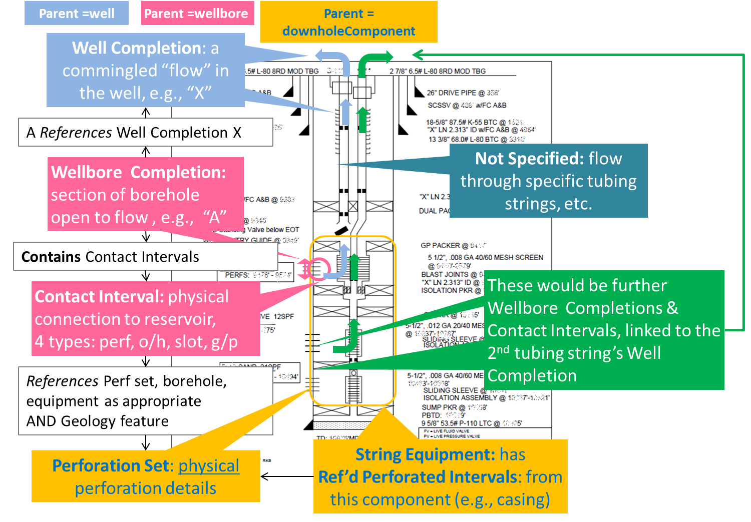
These work together and with other sub-objects in a rather involved way to be able to report flow from defined places along the wellbore to defined surface streams. The following table summarizes how this is done. See also Figure 8.2.5-1 , Figure 8.2.5-1 .
|
Element |
Parent |
Description |
|---|---|---|
|
Well Completion |
Well |
Occurs as a top-level data object. Represents a “flow” or “stream” in the well. The data object also contains business information about this flow, such as field ID, ownership rights, etc. Referenced by the wellbore completion. Multiple wellbore completions can be associated with a well completion. In this way, a commingled set of connections with the reservoir can be associated with a flow within the well. Generally, a well completion is associated with a single “wellhead stream”, i.e., flow from a port in the wellhead. However, this is not always the case. For example, in cases where liquid and gas are separated downhole, the liquid may flow up the tubing and the gas up the casing annulus. In this case, there would be two “wellhead streams” from two ports (tubing and casing annulus), but both would be associated with the same well completion because they both come from the same set of commingled wellbore completions. The wellhead streams are reported in the PRODML Simple Product Volume data object, with a link to the Well Completion. For more information, see the PRODML Technical Usage Guide (Sections 5.2.3 and 6.2.2). |
|
Wellbore Completion |
Wellbore |
Occurs as a top-level data object. Each individual wellbore completion data object represents a completion (i.e., open to flow) interval along a wellbore. Meaning “this section of wellbore is open to flow”. Has data for depth, API numbering, type of fluid, etc. Contains a reference to a Well Completion data object (which is the flow stream from the wellhead), see above. Contains a Contact Interval Set, which represents the physical connection(s) to the reservoir. |
|
Contact Interval Set |
Wellbore Completion |
Occurs in the wellbore completion data object. Contains one or more “xxx interval” objects, each representing the details of a single physical connection between well and reservoir, e.g., the perforation details, depth, reservoir connected. Meaning: this is the physical nature of a connection from reservoir to wellbore. The kinds of interval allowed are:
Each interval has an ID, details about the interval itself, including history, and a reference to the data object giving full details (the kind of equipment is shown in parentheses in the list). |
|
Perforation Set |
Downhole Component |
This section contains information about perforations in the downhole components. Each set has a reference to its related downhole string, and borehole string, and then gives the perforation details. It will be referred to from the perforated type of contact interval. |
|
String Equipment |
Downhole Component |
This section contains the individual items of equipment deployed in the downhole component. A given item of equipment can have a reference to a perforation set, meaning “this item of equipment contains the perforations of this perforation set”. |
Note that flow is not modeled through the components making up the completion (for example, through sliding sleeves, specific tubing strings, etc.). Such a full “flow path” may be added as a later development.